Glyphosate - methods
Our glyphosate pages: Overview | Sites | Experiments | Methods | CRC Hydrology
Autosampling
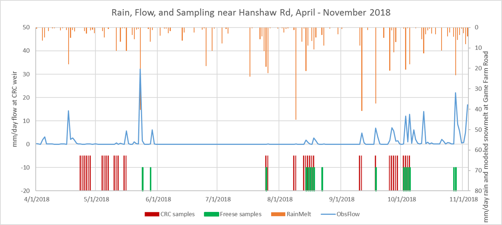
The CRC site’s watershed of 7 hectares and around 1 meter thick of hydrologically active soil reacts quickly to storms and can be almost quiescent hydrologically between storms during warmer months. We need to take many short interval samples for quality testing, to capture possibly rapid dynamics of concentration. We use Teledyne ISCO 6700 portable autosamplers containing 24 1-liter sample containers. (To reduce container cleaning labor and cleaning solvent waste, the containers are single-use plastic bags in durable frames.) The samplers use a peristaltic pump to draw programmed volumes of liquid (“sips”) at programmed times into programmed choices from the 24 containers. The sampler reverses its pump to flush its intake hose before and after drawing a sample, to limit carryover in the hose between consecutive sips. Our programs usually draw a fixed amount of water at 15-30 minute intervals, moving to the next container at 60-240 minute intervals.
We chill the autosampler by including crushed ice in its core, refilled daily. The base of the autosampler is insulated. This is to preserve sample contents against biodegradation1 It is preferable to remove samples within one or two days, but toward the end of a long campaign we are exhausted and compromise by leaving the samples out for a fourth day if the campaign continues that long. We also made a reflective, insulating shroud for the entire autosampler for use during the hottest times of year.
One refinement would be to sip different volumes based on readings from a flow sensor. Outflow at this small, “flashy” site can change quite a bit within a 1-4 hour compositing period. We learned early that glyphosate concentration is correlated positively with flow during an event, thus equal-volume samples from a widely varying flow during a compositing interval will will yield a composite whose concentration is lower than the true mean concentration over the period.
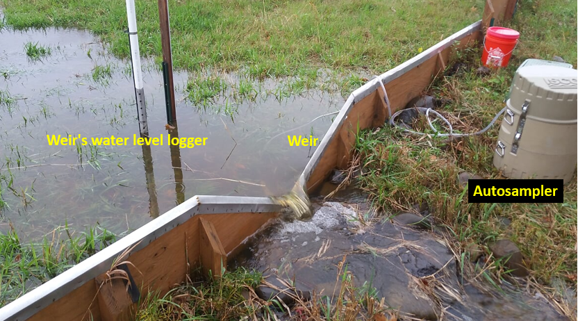
The picture below shows the weir with autosampler at right, its intake hose immersed in the pool above the weir. The water level logger for the weir is inside the white post upstream from the weir’s V. 2018 and later sampling draws from below the weir to take advantage of the mixing while water flows rapidly through the V notch.
Glyphosate Analysis via LC-MSMS and ELISA
The USGS Water Resources Division Organic Geochemistry Research Laboratory (OGRL) in Kansas has a technique termed “LCGY” for analysis of glyphosate, glyphosate metabolite AMPA, and glufosinate in water samples2. For this very sensitive method to be worthwhile, extra care is needed in field sample collection3. Notably USGS never lets LCGY-destined samples touch metal or glass, only plastic. Prior to analysis, all samples are spiked to equal concentrations of heavy isotopic analogs to each analyte, synthesized with heavy carbon13 and nitrogen15. These serve as internal standards. The analytical method derivatizes all analytes, including the internal standards, by reacting with FMOC. The sample is injected into a liquid chromatograph which spreads out the various compounds of the sample over several minutes, then the derivatized molecules proceed minute by minute to a tandem mass spectrometer that fragments compounds in a predictable way. The fragments are the basis for confirming compound identity and quantification. As a quality assurance tactic there are duplicate samples and fortified samples in each batch. Note: The cited 2009 LCGY documentation includes a preliminary step of solid phase extraction (SPE) which cleans up samples and concentrates analytes. OGRL no longer uses SPE.
Initially, Cornell did the sample preparation including internal standard addition and derivatization, prior to sending samples to USGS vialed for use in their LC-MSMS equipment. In 2018 this was changed to have the USGS lab do these steps, after Cornell personnel had made rookie-level mistakes in three groups of samples. The overall LCGY procedure makes it possible to detect many kinds of mistakes and compensates for some.
Using Cornell colleague Ludmilla Aristilde’s lab, our group was able to adapt a simplified version of the LCGY method (without SPE) to analyze 2015 water samples. Some of the archived 2014 samples also were tested, yielding results consistent with preliminary results from nine samples tested in late 2014 by NYSDEC that yielded a 70 µg/L concentration during the first 2014 event peak flow following spraying. (The 2014 trial samples had not been handled consistently with USGS LCGY procedures, notably being acidified to pH 1 at collection. 2014 was a sampling practice year, in effect.) Split 2015 samples with the OGRL had good agreement in results for glyphosate and AMPA. 2016 samples tested using LC-MSMS at Cornell proved to be problematic (clogging the LC column) and we began to use familiar ELISA.
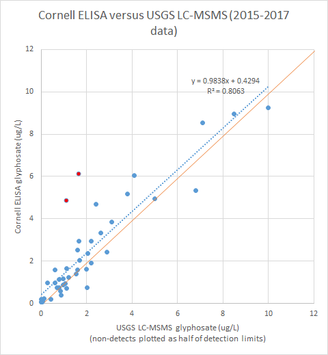
ELISA is a less costly and less respected method for analysis of glyphosate in water samples, which allows us to cover more samples than the USGS lab can cover, and do testing well enough with less specialized and less experienced Cornell personnel in an informal laboratory. We use ELISA kits by Abraxis (later renamed Gold Standard). Compared to USGS LCGY, which can be considered the “gold standard” for glyphosate, ELISA results are less precise, have a higher practical detection limit (0.10 vs 0.02 µg/L), require less manual labor, require simple equipment costing under $5000, and appear to be unbiased. There apparently are no ELISA kits for AMPA. The plot below shows consistency among split samples between the USGS lab and our own ELISA work. This has also been demonstrated by others4. This plot includes split samples from vintages 2015 through 2017.
An important aspect when using ELISA is to build in the kinds of checks used by the LCGY LC-MSMS procedure to enable detection of procedural errors quickly; basic mistakes are common in our Cornell lab group that has a fresh set of mostly inexperienced analytical labor every year, except for one carryover staff member who led the field and lab aspects and maintained procedural documentation.
Water Flowing Out of the CRC Site
At the site’s water exit point we maintain a V-notch weir with a sharp metal crest. Flow is computed using a standard formula Q=f(water height above bottom of V). This requires that the water be unimpeded over the V, i.e. there cannot be back-water effect from downstream. We record water levels in the pool about one meter behind the weir every 5 minutes with a TruTrack Ltd water level sensor mounted in a vertical stilling tube that is perforated and wrapped in mesh to prevent worm and insect entry; the stilling tube is 2-inch PVC pipe with a solid cap on the bottom. The bottom of the pool is a few centimeters below the bottom of the weir’s V notch. The sensor rests in the bottom of the PVC tube which rests on the pool sediment. The tube is clamped to a steel fence post hammered into the pool bed, carefully leveled to vertical at installation. It has not tilted since installation. The zero point of the sensor (as calibrated) is below the bottom of the weir V. The sensor has an internal logger that accumulates data every 5 minutes, downloaded months later. (In 2019 we began to experiment with transmitting readings to Internet as they occur, in parallel with the onsite logging. This was primarily to have real-time site information upon which to base autosampler activation and deactivation. This was discontinued in 2021.)
Problem: The weir was rising out of the ground due to cumulative shrink/swell of the soil and needed to be reinstalled. After reinstallation, the weir remained slightly tilted due to uneven rising. We periodically re-survey to determine the position of the bottom of the V relative to the zero point of the logger.
Problem: The TruTrack logger has outages that may not be detected for months after they occur if the data are not downloaded. This is a second reason for testing Internet transmission of data in real time.
Problem: The TruTrack logger data require extensive processing to filter out individual bad data, to correct timestamps for daylight savings time, and to correct for weir V vertical shifts. It has been taking a year after the orginal readings to make the data usable.
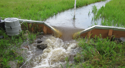
High flow over weir
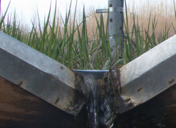
Head-on photo of low flow over V-notch of weir
Piezometer Water Level Measurements
There are 80 piezometers penetrating to the site’s restrictive soil layer about one meter down, 5 per each of the 16 original A-P plots. (Later plots Q and R do not have piezometers as of spring 2019.) These have numbers 1-5 within the plot, 1 at west and 5 at east. They represent different probabilities of water saturation within the plot, which is correlated with a tendency for the soil to become anaerobic. Water levels in most of these were measured manually during the growing season at intervals of weeks to months. Thus the data are primarily spatial, secondarily temporal. One set of 80 manual readings takes a couple of hours when only water levels are being read. Most piezometer water levels were measured using a graduated, solid bottomed tube that we inserted slowly into the piezometer while listening and feeling for a “plunk” when it touches the water surface. Measured values are depths below the rim of the piezometer, which may be slightly above or slightly below the local land surface. The land surface elevations above sea level at the piezometers are known indirectly from our County’s 2008 aerial LIDAR measurements on a fine grid. The vertical positions of the piezometer rims relative to the land surface are measured occasionally. Combining the various vertical measurements allows converting water levels or depths to elevations above sea level, so that levels in different piezometers can be compared such as by mapping.
A few piezometers had TruTrack water level sensors hanging downward from their rims. The TruTrack device reports millimeters of water above its zero point. The vertical position of the zero point relative to the land surface was measured at installation and occasionally afterward. Like the weir flow data, piezometer data require extensive processing before use.
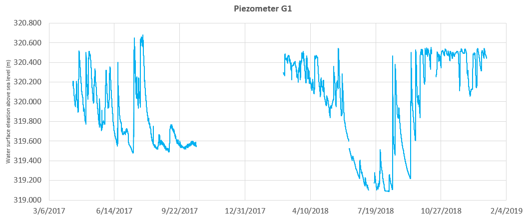
Time plot of partially processed piezometer G1 water levels
Soil Moisture
Volumetric soil moisture has been measured by three methods: continuous capacitive sensors with loggers, TDR devices, and gravimetry. In 2019 there were three locations hosting pairs of capacitive sensors. Each pair consisted of shallow and deep sensors, and there was also a soil temperature sensor at a depth between the two moisture sensors. One long-standing set of sensors was at the meteorology station and was last being logged at 1 hour intervals after a long period logged at 0.1 second intervals together with wind data. The other two installed trios ware at the same subplot locations as piezometer level sensor/loggers. These dated from 2018 and logged at 1 hour intervals. All moisture sensors were from the Spectrum corporation.
The TDR and gravimetric surveys covered all of the 88 subplots of the site and were done primarily during greenhouse gas sampling campaigns.
Atmospheric
The onsite meteorology station measures incoming solar radiation, 3-D wind speeds at a few meters above ground, air temperature, relative humidity, and precipitation. The precipitation gauge does not melt snow. Measuring rainfall on the site was unnecessary prior to the glyphosate work, thus no maintenance experience or regime has been evolved. The accumulated onsite precipitation data have proven problematic and are generally not usable. The other meteorology data are useful in hydrology work, made more usable after the recording interval was reduced in 2018 from ten per second (dictated by 3-D wind speed recording) to the order of minutes.
To provide essential precipitation data including for the winter, Cornell’s Game Farm Road meteorological station, 3.5 kilometers from our CRC site has been used. This provides daily data on a 7am to 7am basis, using local time incorporating daylight saving time. Data are acquired from NOAA’s Climate Data Online. While we do not sample for glyphosate in winter, hydrology work in this region requires some attention to snow dynamics. The Game Farm Road station provides sufficient data in winter to apply a simple method of modeling snow5 which can be checked against the station’s observed snowfall and snow accumulation data.
Another Cornell unit formerly operated a Rainwise weather station that published its short-interval data to internet. This was at the same site as the official daily station, which provided a means to cross-check all-important precipitation data. Since that Rainwise station ceased to publish during summer 2018, nearby amateur stations that publish on Weather Underground have filled the gap. (Station KNYITHAC70 is an Ambient Weather station operated by one of our staff at home.) As with the former Cornell Rainwise station, precipitation from the amateur stations must be cross-checked against 7am-7am daily totals from the curated, official data from the Cornell official station. None of the amateur stations melts snow as it falls, thus their total precipitation timing data are only usable during snow-free seasons which are typically mid-April through early November. The map below shows the locations of the amateur and official stations relative to the sampling sites.
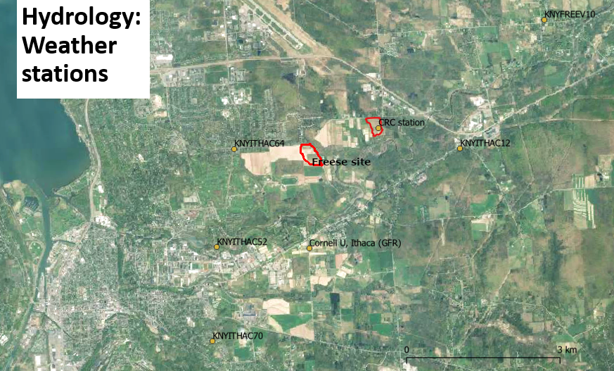
Location of meteorological stations relative to sites
In 2020 we added an onsite amateur station to the site, model WS-2902 by Ambient Weather. It does not melt snow actively thus its precipitation data do not represent winter snowfall and any large snow events will overflow its catch cone; winter precipitation data probably represents timing of radiation and temperature driven melt timings, but not quantities.
Later hydrology work at the same site
There is deeper and later coverage of the meteorology and hydrology measurment techniques and data interpretation at another group of web pages by the Soil and Water Lab, termed CRC Hydrology and linked in the headings of each page of this web collection.
Last updated 2023-09-21 sp17 AT Cornell.edu.
Footnotes
Kylin, H. 2013. Time-integrated sampling of glyphosate in natural waters. Chemosphere 90:182101828. DOI↩︎
Michael T. Meyer, Keith A. Loftin, Edward A. Lee, Gary H. Hinshaw, Julie E. Dietze, and Elisabeth A. Scribner. 2009. Determination of Glyphosate, its Degradation Product Aminomethylphosphonic Acid, and Glufosinate, in Water by Isotope Dilution and Online Solid-Phase Extraction and Liquid Chromatography/Tandem Mass Spectrometry. Techniques and Methods 5-A10. URL, DOI.↩︎
U.S. Geological Survey, 2006, Collection of water samples (ver. 2.0): U.S. Geological Survey Techniques of Water-Resources Investigations, book 9, chap. A4, September 2006, accessed 2019-05-01, at URL.↩︎
Sanchis, J., L. Kantiani, M. Llorca, F. Rubio, A. Ginebreda, J. Fraile, T. Garrido, and M. Farré. 2012. Determination of glyphosate in groundwater samples using an ultrasensitive immunoassay and confirmation by on-line solid phase extraction followed by liquid chromatography coupled to tandem mass spectrometry. Anal Bioanal Chem 402:2335-2345. DOI.↩︎
M. Todd Walter, Erin S. Brooks, Larry G. King, Donald K. McCool, Myron Molnau, Jan Boll. 2005. Process-based snowmelt modeling: does it require more input data than temperature-index modeling? Journal of Hydrology, 300: 65-75. DOI.↩︎