Methods detail - monitor wells
1. Situating wells
We locate a temporary monitor well so it is downgradient or upgradient from pesticide use areas, drawing upon insight about the direciton of groundwater flow on the property. There are often indicators of the water table visible, and we can often infer from topographic maps overlaid on aerial photographs. Particularly LIDAR maps are helpful. (See Methods detail - site characterization).
The owner must approve the locations of wells. They often have excellent insights about groundwater presence and flow direction.
It is essential to protect buried utilities when installing wells using power equipment such as our auger trailer. We make a UDigNY filing when necessary. The cooperating landowners will know about most buried utilities.
2. Installing driven wells
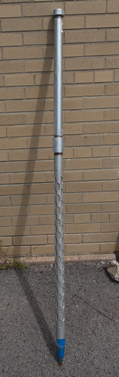
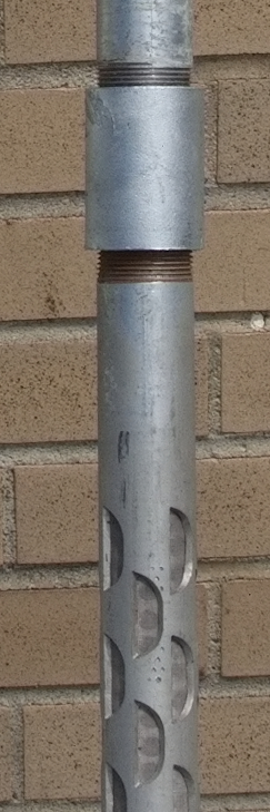
A driven well is galvanized steel (Figure 1), of a type typically used for drinking water. Sometimes these are called “sandpoint” wells. It consists of a “point” at the bottom, which is a tapered solid tip, then a constant-diameter section with holes lined by screening of 0.01 inch mesh size (Figure 2). Then one or more solid pipe segments are attached via threaded female-to-female drive couplings that are hardened to survive the installation pounding force. We use a potable grade grease (pipe dope) inside the couplings to make the joint water tight and to enable strong tightening. At the very top we provide a cap.
The well is forced into the ground by pounding it with a heavy well hammer. Initially we make a 3-foot hole with a post-hole digger. As we pound the well farther in, we attach more and more 2-4 foot pipe segments and couplings. Periodically we check the water level inside with a sounder (go to section 1.). When the well has at least one meter of water in it, we declare success. It may take some time for the water level to rise inside the pipe. If we install during a higher water table season, we typically want more than one meter of water at installation time so that there will be one meter during dry seasons in case we want to sample then.
We can measure the total depth of the installed well, below the rim, by sending the sounder probe all the way to the bottom with the beeper turned off. The touch on the bottom can be felt in the cable.
After the well is at the desired depth, we fill in the surface post-hole with local soil and bentonite powder, to seal the well against water running down from the surface. We then let the well rest for a day or more.
We return at least a day later to develop the well by surging it with a pole terminated in a bottom piece that is almost the same diameter as the inside of the well point. This will usually make water flow better through the screen if there are any fine particles present around the screen.
3. Installing augered wells
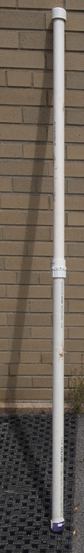
Augered wells can be either PVC or steel. We prefer PVC, but sometimes we need to pound in the well deeper in the augered hole and for that we must use steel (same as for driven wells). PVC wells (Figure 3) use a slotted section at their bottom, with slots 0.01 inch openings, instead of screening (Figure 4).

An augered monitor well is installed using a screw auger to make a hole, then inserting a preassembled well (screen then solid pipe) into the hole, and backfilling the borehole around the well. The backfill begins with sand poured into the hole with nominal diameter larger than the screen. We add about 25 pounds of sand into the hole, enough to entirely cover the well screen. Then we add an inch or two of bentonite powder which will swell when moistened. We then add a slurry of what the auger brought up, plus more bentonite, pressing the slurry downward into the borehole. We ultimately reach the surface and we mound up the slurry around the well a little.
The auger is raised and lowered during the drilling to empty off material that it has cut through. It is easy to tell when the water table has been reached because what is brought up on the auger screw is saturated. We keep going until we are at least two meters down. We can probe the hole with a surging rod (minus larger diameter tip) as described in the previous section, to see how deep the well actually is. We can also measure the water level in the borehole with a sounder.
When we must drive the well deeper than we can reach with the auger, we usually have been able to use a poundable steel well and the well hammer to drive it several feet deeper.
Development is identical to driven wells.
4. Use in teaching
A Cornell undergraduate groundwater class, co-taught by SWL faculty and Cornell Earth and Atmospheric Sciences faculty, has installed driven and augered wells on a Cornell property near Ithaca that has shallow groundwater. The class also made field measurements and collected water samples.
5. HowTo in greater detail
Last updated 2023-08-17, sp17 AT Cornell.edu.